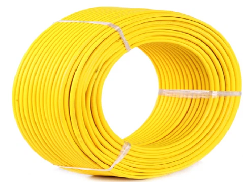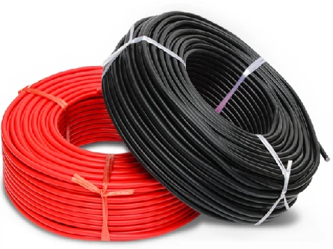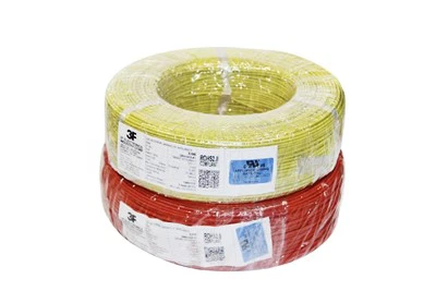

The model and specifications of the vehicle instrument leads (wires or harnesses connecting the instrument panel to various sensors and control units of the vehicle) need to be determined according to the vehicle type, instrument function, electrical parameters, and industry standards. The specifications vary greatly in different scenarios. The following are common model specification classifications and explanations:
1.Wire material and insulation layer type
(1)Wire material
The mainstream is copper core wire (pure copper or high-purity electrolytic copper) with good conductivity; Some high-temperature environments (such as leads near the engine compartment) may use tin plated copper cores to enhance corrosion resistance and oxidation resistance.
Special scenarios (such as vehicles with high lightweight requirements) may use copper-clad aluminum wire, but its conductivity is slightly lower and its application is limited.
(2)Insulation material
Ordinary environment: PVC (polyvinyl chloride), low cost, good insulation, suitable for normal temperature environment in the cockpit (-40℃~125℃).
High temperature environment (such as near the engine or exhaust pipe): XLPE (cross-linked polyethylene) or silicone rubber, with a temperature resistance range of -60℃~150℃ or even higher.
Wear resistant/oil resistant scenarios: chloroprene rubber (-60℃~125℃), cross-linked fluororubber (-60℃~200℃) or polytetrafluoroethylene (PTFE) (-60℃~260℃), suitable for areas in contact with engine oil and fuel.

2.Wire cross-sectional area (wire diameter) specification
Wire diameter is a core parameter determined by the current passing through, wire length, and allowable voltage drop, typically measured in square millimeters (mm2) or American Wire Gauge (AWG).
Small current signal leads (such as speed, water temperature, and oil level sensor signal transmission): The cross-sectional area is usually 0.3mm2~0.75mm2 (corresponding to AWG 22~18), and the current is generally≤1A.
Medium current leads (such as instrument backlight and indicator light power supply lines): with a cross-sectional area of 0.75mm2~1.5mm2 (AWG 18~16) and a current of 1A~5A.
High current leads (such as instrument power supply main line, heating function leads): cross-sectional area can reach 2.5mm2~4mm2 (AWG 14~12), current 5A~10A (depending on power calculation, larger wire diameter may be required for instrument heating wire power supply).
3.Wire color and identification
For the convenience of installation and maintenance, the lead color must comply with industry standards (such as ISO, SAE, or custom specifications of automotive companies). Common colors and meanings:
Positive pole of power supply: Red, Brown
Negative/Grounding: Black, Grey
Signal transmission lines: yellow, green, blue (often with stripes, such as yellow/black, green/white, to distinguish different signal types, such as speed signal, water temperature signal).
4.Wire harness structure and protection specifications
(1)Single core and multi-core
Most instrument leads are single core wires (single or multiple stranded), while multi stranded wires (such as 7-stranded 0.16mm copper wire) have better flexibility and are suitable for environments with frequent vibrations.
Partial integrated signal leads may use multi-core shielded wires (such as with aluminum foil and braided mesh shielding layer) to resist electromagnetic interference (EMI) and avoid interference with precision signals such as speed and vehicle speed.
(2)Wire harness protection
Exposed leads may be covered with corrugated pipes (PP or PA materials) or woven mesh tubes to enhance wear resistance and bending resistance.
The lead wire passing through the metal hole needs to be protected with a rubber sheath to prevent the insulation layer from being cut by sharp edges.
5.Industry standards and model identification
(1)International standard
Following ISO 16942 (Road Vehicles - Low Voltage Cables) or SAE J1128 (Automotive Electrical Wiring), the standard specifies the temperature resistance level (such as 105℃, 125℃) and voltage resistance performance (usually≥300V AC) of the wire.
Model identification example: "FLRY-B 0.5mm2" (FLRY is the code for automotive low-voltage wires, B represents thin-walled insulation, and 0.5mm2 is the cross-sectional area).
(2)Customized specifications for car manufacturers
Different car companies (such as Toyota and Volkswagen) will develop internal specifications based on international standards, such as wire color coding, shielding layer thickness, etc. Specific models need to refer to the maintenance manual of the corresponding model (such as Volkswagen's "VW 60306" standard).

6.Example of typical application scenarios
Car instrument signal wire: mostly 0.3mm2~0.5mm2 single core PVC insulated wire, with stripes in color (such as green/yellow for speed signal), in compliance with ISO 16942 Class B (thin-walled).
Commercial vehicle instrument power cord: Due to high current (such as instrument backlight+sensor power supply), a 1.0mm2-1.5mm2 tinned copper core wire with insulation layer temperature resistance of 105℃ may be used.
New energy vehicle instrument high-voltage signal lead: It needs to meet additional high-voltage insulation standards (such as UL 94 V-0 flame retardant rating), with a cross-sectional area of up to 2.5mm2 or more and a double shielding layer.
In short, there is no unified "fixed value" for the model specifications of vehicle instrument leads, which needs to be determined based on the electrical design drawings or maintenance manuals of specific vehicle models. If procurement or replacement is required, it is recommended to refer to the part numbers provided by the vehicle manufacturer (such as Bosch, Continental's instrument harness numbers) or the parameters on the wire identification (cross-sectional area, temperature resistance level, etc.).